

How to Create a Scale Drawing of a Room TUTORIAL
Brand Your Own Blueprint
How to Draw Floor Plans by Hand or with Home Design Software

This Make Your Own Design tutorial will walk you lot through the detailed steps of how to draw floor plans for your new home blueprint. This procedure can be followed by those drafting their blueprints by hand or using abode pattern software.
For this tutorial, we are assuming that you have already completed your house design sketches. If yous are just starting out with your domicile design, check out our free Home Design Tutorial.
Page Sections at a Glance
- Drafting Options
- Tools to Make Your Ain Blueprints
- Using an Architect'due south Scale
- The Blueprint Page Itself
- Draw Exterior Walls
- Draw Interior Walls
- Locate Doors and Windows
- Draw Electrical Symbols
- Label Flooring Surfaces
- Dimension Your Plans
- Add Furniture
- Create Window Schedule
Drafting Options
There are basically 2 ways to brand your own blueprints.
- Using home pattern software
- Drafting past hand
At that place is likewise the option of doing a flake of both.
Some may ask why would anyone make their own blueprints by mitt when we take many relatively inexpensive home blueprint software products available.
Here are some practiced reasons:
- It takes a long time to truly learn how to utilise the house design programs to completely generate the cross sections, framing and other design details that you demand to get your building plans approved.
- Most of the inexpensive programs (less than $250) exercise not generate the kind of details required for full construction drawings.
Most of the home design programs can produce accurately dimensioned floor program drawings of the quality required for your building permit. But for some programs this is as far equally you can go with the construction drawings. What views remain are the cross-sections, meridian views, and any necessary framing plans. This is where you lot may take to make your ain blueprints by hand or use a more than total-featured (and more expensive home design program).
I am non suggesting to stay abroad from home design programs entirely. Rather a adept approach if you lot want to go on costs down is to do some cartoon with design software and some hand drafting.
The home pattern programs are bang-up for allowing yous to draw floor plans in 2D then visualize them in 3D. You can easily move walls as you refine your pattern. The design programs allow you lot to chop-chop generate views of your ideas and designs. You can then easily alter the drawings every bit you lot drag and drop furniture, appliances and fixtures into the blueprints. Oft, you'll realize not enough space has been allowed for sure areas once the fixtures are in or perhaps you are wasting space in some areas.
Whether yous are using dwelling house design software or cartoon your blueprints by mitt, the first drawings to showtime with are your floor plans. Using your ain floor plan sketches or your results from the Draw Flooring Plan module of our house design tutorial, start past cartoon the exterior walls of the main story of your home. (The sequence detailed below for drawing floor plans by hand is a practiced one to follow if you are using design software as well.)

Your local art supply store should take all the of drawing tools yous will need to make your own blueprints. You can also order most of these supplies online. A good supplier is Utrecht Drafting Supplies.
- Architect'due south scale
- T-foursquare
- Adaptable triangle
- Mechanical pencils with leads
- Felt tip pens
- Erasers
- Erasing shields (for accurate erasing of merely specific parts of your drawing)
- Compass
- Symbol template
- Long metal ruler or straight edge
- Tracing paper
- Masking tape
- Utility pocketknife
- Big apartment working surface (table)
- White affiche board as a base for your working surface
Optional merely dainty:
- Parallel ruler (for drawing parallel lines — alternatively you lot tin also use a T-square)
How to Apply an Architect'southward Scale
To brand your ain pattern to scale you lot will use an architect's scale. Architect's scales are very elementary to use, no math required.
For house plans, you should be using a scale of one/four inch to a human foot for the floor program drawings. This is written as i/4":1'. This ways that every quarter inch you draw on your page represents one foot for the real house as it volition be built. So 1 inch on your drawing would represent 4 feet of the built house.
Observe the side of the triangular scale which has ane/4":1' marked on it. The numbers on this side of the scale represent feet for your built firm. So if yous needed to draw an exterior wall 36 feet long, you would:
- Lay the scale down on the paper
- Make a small pencil marking on your newspaper by the cipher mark on the calibration
- Brand some other small pencil mark on your paper past the 36 mark on the scale
- Use your metal straight edge to draw a directly line connecting the two marks.
This line would measure 9 inches on your drawing and would represent 36 feet for the built house.
When finished your drawings must have all room dimensions accurately marked. Just building trades people will ofttimes use an architect'south scale (or ruler) while they are edifice to check diverse dimensions on your drawings. And so for this purpose make sure that y'all use you scale accurately for every line you describe.
The Blueprint Page Itself
To make your own pattern flooring plans, use a sheet of paper 24" by 36". Lay the sheet downwardly on your working surface with the longest edge running horizontally.
The lower correct hand corner of your drawing you will save for your title block. This is where you will write the proper noun of the view yous are drawing (floor program, elevation, cross section), the scale of the cartoon, the name of the business firm (could just be the family proper noun), designer's proper name and date. The date is very important specially when yous brand changes to your plans. Everyone on the building site needs to know what date version of the plans they should be using.
We ran into this outcome when our concrete footings and post pads were being poured. Luckily I was watching the cascade when I noticed the pads for the structural posts were being poured in the wrong location. I talked with the crew and institute they had an erstwhile set of drawings. We moved the forest framing for the pads and and so paw shoveled the poured concrete over to the right location.
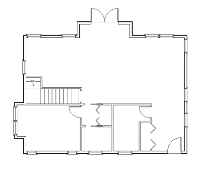
Describe Exterior Walls
Start by drawing the exterior walls of your design. You volition want to roughly center your commencement floor plan view in the infinite on the newspaper available excluding the title block. So before you depict your first wall, utilize your calibration get a rough idea of how much space on the page your start flooring programme volition need.
For this tutorial nosotros will move in a clockwise direction starting at the upper left hand corner of your cartoon. You can choose how you will orient the dwelling house on the page. It is fairly standard to have the front end door at the lower side of the horizontal sheet but depending on the design or shape of your home yous may want to alter this.
For the floor program drawings yous volition draw the framed walls, interior and exterior. That is you volition not exist drawing the finished dimensions of the rooms once drywall or other finished wall surfaces are installed. Other drawings will detail finished surfaces of exterior and interior walls as required.
The construction drawings for the floor plans need to exist properly dimensioned for the framing crew. The room size departure with the drywall installed is very pocket-sized and volition simply make about an inch of departure for whatever given room (a one-half inch of drywall on either side of the room). Just there may be parts of your design where being out past an inch will cause bug (for instance if you are pre-ordering custom or stock cabinetry).


Start from the upper left hand corner of your floor plan design. At this point do not worry nearly doors and windows, we will depict them in later.
- Utilise a pencil, your builder's scale and a straight edge to draw what the total inside dimension of the commencement wall will exist until it meets another wall (your exterior walls could exist anywhere from several inches to a couple of feet thick—for a straw bale home for instance).
- Use your T-square (or a protractor for a wall not at a square angle to the previous wall) and architect'due south scale to draw the next wall.
- Go on in this fashion, clockwise around your drawing until the inside framing side of all of yous exterior walls are drawn.
- Finally, draw the outside of the exterior wall framing. If you are framing with 2 by 6s, your outside framed walls will be five i/2 inches thick (ii by 4s and 2 by 6s are run through a planer that takes a one-half inch off both their width and thickness).
Draw Interior Walls

For your interior walls:
- Draw both sides of each interior wall. If you lot will exist using ii by 4s to frame your interior walls, the actual thickness of each framed wall will be 3 1/2 inches (as explained to a higher place at the end of the drawing outside walls section). Initially, just draw each wall, we'll locate doors and whatsoever openings afterwards.
- Draw walls effectually any stairwell areas. This helps visualize the stairwell surface area as a room. If in that location volition non be a physical wall around the stairwell simply depict a faint dotted line.
- Draw staircases and any mid-stair landings within these walls.
- Draw an pointer labeled "up" in the up direction of the stair.
Draw Doors and Windows
The next step equally you make your ain blueprint is to draw your doors and windows onto the flooring plan. For each door, window or wall opening on your floor plan:
- Apply your scale to locate its position.
- Draw the advisable door or window symbol from the blueprints symbols glossary to properly identify it.
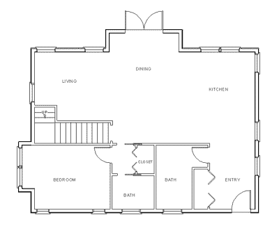
Label Rooms
In the center of each room, conspicuously label the room name. Include closets and open spaces such as entrances.
Locate Appliances, Plumbing and Fixtures
Using your scale, symbols template and directly edge, draw the correct symbols for:
- All appliances
- Congenital in furniture such as kitchen and bathroom cabinets and counters
- Plumbing items such every bit sinks, toilets and tubs
- Fireplaces
- Equipment such as furnaces, air conditioning units and water tanks.

Draw Electrical Symbols
All electric symbols should at present exist added to your plans.
- Plug outlets
- Wall switches for lights or switchable plugs
- Wall light such as sconces
- Doorbells
Place the advisable symbols forth walls for the following electrical items:
For ceiling mount items, depict the following fixtures on the flooring just below the spot where the item would exist installed.
- Ceiling lights such as pot lights or track lighting.
- Smoke alarms
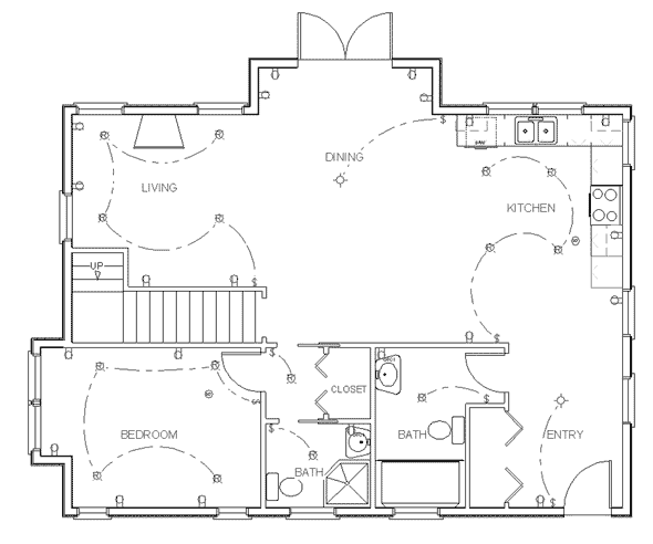
Label Floor Surfaces
Detail the plans by indicating for each room how the floors will be finished and any required sub-flooring. For instance your plans may read:
- three/iv" hardwood flooring
- 1/4" tile over 1/2" plywood sub-flooring
- Rug over 5/8" plywood sub-flooring

Dimension Your Plans
The next step on your floor programme drawings is to draw authentic dimension lines. Yous will need to draw dimension lines for:
- Each room
- Closets
- Cabinet depths
- Distances from wall to dorsum of toilet (know as the rough in dimension)
- Sizes of tubs
- Distances from walls to edge of any appliances or fixtures.
Annotation that not all required dimension lines are shown in the plan below—this is for ease of viewing. 1 more dimension line should run forth each exterior wall to locate all window and door openings.

Add together Furniture
Article of furniture should not be included in your construction drawings just for your own blueprint purposes it is a good idea to employ scaled furniture cutouts during the blueprint process to ensure you have designed adequate space for all rooms and circulation paths. See our tutorial module Draw Floor Plan for more information and article of furniture blueprint symbols.

Create Window and Door Schedule
The last stride to make your ain blueprint is to create a window and door schedule.
On your floor plan:
- Label each door and window with a number or letter.
- In a blank area to the correct of the floor programme, create a iii column list.
- Put all the labels for your door and windows in the first column.
- List window and door types in the second column (casement, awning, fixed, single hung, etc.)
- List the exact window size in the third cavalcade.
Next Make Your Own Pattern Module
Go along on to the next house construction drawing tutorial modules: How to Describe Elevations and Drawing House Cross Sections.
No part of this web site may exist reproduced or copied without written permission. Illegal Cyberspace copies will be detected by Copyscape.

DOWNLOAD HERE
How to Create a Scale Drawing of a Room TUTORIAL
Posted by: robertlany1985.blogspot.com

Comments
Post a Comment